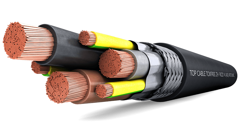
TOPDRIVE VFD (EMC) ROZ1-K (AS) 0,6/1kV and 1,8/3kV cable for marine installation has been designed for installation on ships and vessels' machine rooms, where VFD Motors are located. This is a flexible cable for fixed installations, for variable speed motors or pumps. The cable is designed according to the toughest requirements of IEC60092-350 and IEC60092-353 standards for shipboard applications.
TOPDRIVE VFD (EMC) ROZ1-K (AS) cable performance
Electrical performance
LOW VOLTAGE 0,6/1 kV (also available at 1,8/3kV)
Standard
IEC 60092-353
Approvals
BUREAU VERITAS / DNV-GL / ABS / LLOYD'S REGISTER / RoHS / CE / UKCA
CPR Construction Product Regulation
Cca - s1a, d1, a1
Thermal performance
Maximum conductor temperature: 90ºC.
Maximum short-circuit temperature: 250ºC (max. 5 s).
Minimum service temperature: -40ºC (fixed and protected installations).
Fire performance
Flame non-propagation based on EN 60332-1 and IEC 60332-1.
Fire non-propagation based on EN 60332-3/IEC 60332-3 and EN 50399.
Reaction to fire CPR: Cca - s1a, d1, a1 , according to EN 50575.
LSHF (Low Smoke Halogen Free) according to EN 60754-1 and IEC 60754-1.
Low smoke emission based on EN 61034 and IEC 61034.
Light transmittance > 80%
Low corrosive gases emission based on EN 60754-2 and IEC 60754-2.
Mechanical performance
Minimum bending radius: x10 cable diameter.
Impact resistance: AG2 Medium severity.
Environmental performance
Chemical & Oil resistance: Acceptable.
UV resistant based on EN 50618.
Water resistance: AD5 Jets.
Other
Meter by meter marking.
Ripcord.
Electric fields resistant.
Installation conditions
Open Air.
Buried.
In conduit.
Applications
Shipboard installation.
Installation on vessels.
Electromagnetic protection.
Variable Frequency Drive (VFD).
Electromagnetic protection.
TOPDRIVE® VFD (EMC) ROZ1-K (AS) for marine installations cable design
Conductor
Electrolytic annealed copper conductor, class 5 (flexible), according to EN 60228 and IEC 60228.
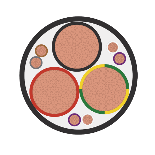
Protective Conductor
The ground conductor is divided into three conductors; the equivalent cross-section is approximately 50% of the section of the phase conductor. For 4G cables, ground conductor has the same cross-section as the phase conductors.
Insulation
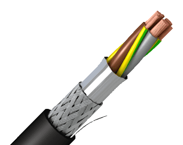
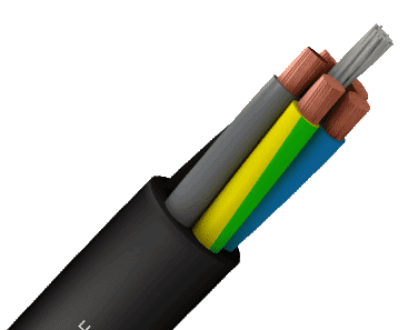
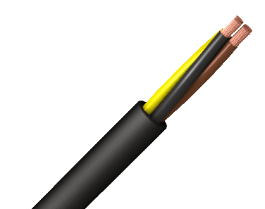
Cross-linked polyethylene type HF XLPE 90ºC according to IEC 60092-360. The standard identification of insulated conductors is the following:
3 x + 3 G Grey + Brown + Black +Green/yellow (3 G) (from 6mm2 onwards)
4 G Grey + Brown + Black + Green/yellow (up to 4 mm2)
Assembly of cores
For 3 x + 3 G cables, the three phase conductors are cabled helically with the three protective conductors distributed in the interstices. For 4 G cables, the three phase conductors and protection conductor are cabled helically.
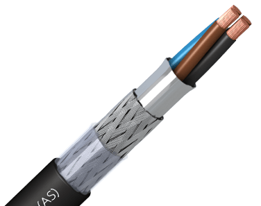
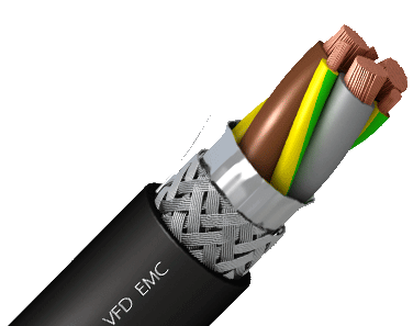
Screen
Aluminium-polyester tape screen, helically placed over the insulated conductors. Over the tape there is a tinned copper braid screen. The tape and the braid act as a double screen to cut out all of the electromagnetic interference, with a minimum total section of 10% of the phase conductor, ensuring a total shielding coverage.
Outer sheath
Polyolefin LSHF outer sheath type SHF1 according to IEC 60092-360. black color. The ripcord allows you to tear the outer sheath without damaging the screen.